
はじめに
Cisco Catalyst 4500-X で 2 台のスイッチを冗長化する際に用いられるのが VSS(Virtual Switching System)です。コア/ディストリビューション層で STP に頼らない冗長構成を組みたい場面で、設計から設定、障害対策までを一通り押さえておきたい技術です。
本記事は、VSL の作成からコンバージョン、Dual Active Detection(DAD)までの設定手順を、Cisco 公式リファレンスに沿って整理した実務向けの備忘録です。
- VSS の基本構成と、構築前に決めるパラメータ・設計上の制約
- VSL 作成からコンバージョンまでの設定手順(コマンド例つき)
- スプリットブレインを防ぐ Dual Active Detection の設定
- サポート終了後の選択肢(StackWise Virtual/Nexus vPC との違いと移行の考え方)
結論を先に整理すると、VSS は 2 台の筐体を論理的に 1 台として扱う冗長化技術で、VSL は LACP を使わず mode on で構成するのが要件です。VSL 全断時のスプリットブレインに備えて DAD を併用することが推奨されます。なお Catalyst 4500-X はすでに公式サポートが終了しており、新規・更改では後継の StackWise Virtual(SVL)への移行が現実的な選択肢になります。
VSS(Virtual Switching System)とは
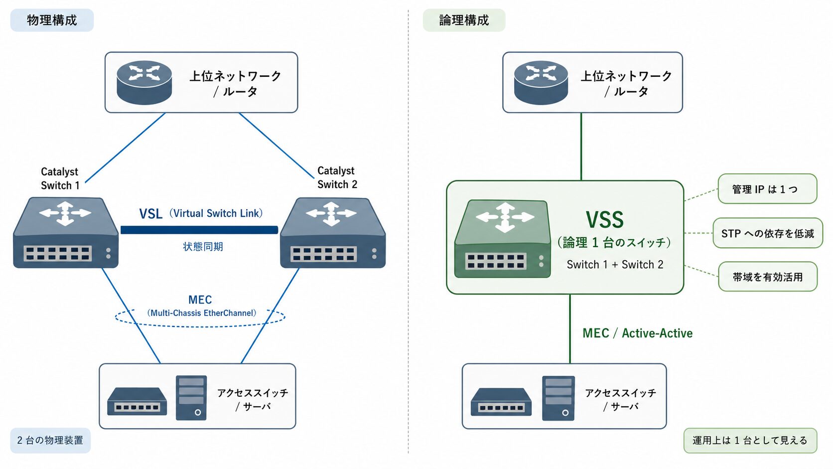
VSS は、2 台の物理的な Catalyst スイッチを論理的に 1 台のスイッチとして動作させるクラスタリング技術です。
通常、2 台のスイッチを冗長化すると、スパニングツリープロトコル(STP)によって片方のリンクがブロックされ、帯域を使い切れないことがあります。VSS を構成すると、次のような利点があります。
- 論理 1 台化: 管理 IP が 1 つになり、運用負荷を低減できる。
- STP への依存低減: ループ構造がなくなり、複雑な STP 設計を避けられる。
- 帯域の有効活用: 2 台のポートをまたぐ Multi-Chassis EtherChannel(MEC)を組めるため、Active/Active で帯域を活用できる。
VSS は元々、大規模コアスイッチである Catalyst 6500 シリーズ向けの技術でしたが、その後 Catalyst 4500-X や 4500-E でもサポートされました。現行の Catalyst 9000 シリーズでは、同等の概念が StackWise Virtual(SVL)という名称に置き換わっています。コマンド体系は一部異なりますが、専用リンクで状態を同期する点や、Dual Active 対策が必要になる点は VSS と共通です(詳細は後半の比較セクションを参照)。
構築前のパラメータ設計と注意すべき制約
設定中に迷わないよう、以下のパラメータを事前に設計しておきます。
- Virtual Switch Domain ID(1〜255)
-
VSS のペアを識別する ID。同一ネットワーク内に複数の VSS ペアがある場合は、重複しない ID を割り当てます(仮想 MAC アドレスの競合を避けるため)。
- Switch ID(1 または 2)
-
どちらの筐体をスイッチ 1/スイッチ 2 とするかを定義します。
- Switch Priority(任意)
-
どちらを Active(主系)にしたいかを決めます。デフォルトは 100 で、Active にしたい側を高く設定します(例: 200)
- Switch 1(Active 予定): Priority 200
- Switch 2(Standby 予定): Priority 100
- Domain ID: 100
- VSL(Virtual Switch Link): 状態同期用の専用リンク(10G ポート × 2 本で Port-Channel を組むのが一般的)
設定前に知っておきたい制約
手順そのもの以上に、運用判断に関わる制約を押さえておくと安全です。
- プリエンプション非対応
-
すでに片方が Active として稼働している場合、もう一方は priority が高くても Standby になります。priority 設定だけでは Active 側を確定できない点に注意します。
- VSL 設定時の構成削除
-
VSL に指定したインターフェースは、一部の許可コマンドを除いて既存設定が削除され、制限モードになります。
- SSO / NSF 前提
-
VSS は SSO 冗長を前提としており、要件を満たさないとペアを確立できません。両筐体で同一の IOS イメージとライセンスレベルをそろえる必要があります。
参考: Configuring Virtual Switching Systems (Catalyst 4500 Series, IOS XE 3.8.xE)
“Because preemption is not supported”
(プリエンプションはサポートされないため、先に Active になった側が役割を保持します)
https://www.cisco.com/c/en/us/td/docs/switches/lan/catalyst4500/XE3-8-0E/15-24E/configuration/guide/xe-380-configuration/vss.html
Catalyst 4500-X VSS の設定手順
ここからは、VSL の作成 → ドメイン定義とコンバージョン → DAD の設定 → 確認、の順に進めます。本セクションのコマンドは、上記の Cisco 公式設定ガイドおよび TAC ドキュメントで確認した内容に基づいています。
まず、2 台のスイッチをつなぐ VSL を作成します。VSL には設定情報やステータス同期などの制御パケットが流れます。
ここで重要なのが、VSL の EtherChannel は mode on(強制)で構成し、LACP や PAgP などのネゴシエーションプロトコルは使用しない点です。VSS の同期プロセスはスイッチ起動の早い段階から始まるため、ネゴシエーションを待たずにリンクアップさせる必要があります。
Switch 1 の設定:
Switch-1(config)# interface port-channel 10
Switch-1(config-if)# switchport
Switch-1(config-if)# switch virtual link 1
Switch-1(config-if)# no shutdown
Switch-1(config-if)# exit

Switch-1(config)# interface range tenGigabitEthernet 1/1 - 2
Switch-1(config-if-range)# channel-group 10 mode on
Switch-1(config-if-range)# no shutdown
Switch-1(config-if-range)# end
Switch 2 の設定:
Switch-2(config)# interface port-channel 20
Switch-2(config-if)# switchport
Switch-2(config-if)# switch virtual link 2
Switch-2(config-if)# no shutdown
Switch-2(config-if)# exit

Switch-2(config)# interface range tenGigabitEthernet 1/1 - 2
Switch-2(config-if-range)# channel-group 20 mode on
Switch-2(config-if-range)# no shutdown
Switch-2(config-if-range)# end
ここでは物理ポート Te1/1 と Te1/2 を使用する例としています。この時点では、2 台はまだ独立したスイッチとして動作しています。
参照: Cisco Catalyst 4500 Series VSS 設定ガイド(https://www.cisco.com/c/en/us/td/docs/switches/lan/catalyst4500/XE3-8-0E/15-24E/configuration/guide/xe-380-configuration/vss.html)
VSL の設定が完了したら、ドメイン ID を割り当て、変換モード(Conversion)を実行します。
まず、決めておいたドメイン ID、スイッチ ID、プライオリティを設定します。
Switch 1(Active 予定)の設定:
Switch-1(config)# switch virtual domain 100
Switch-1(config-vs-domain)# switch 1
Switch-1(config-vs-domain)# switch 1 priority 200
Switch-1(config-vs-domain)# switch 2 priority 100
Switch-1(config-vs-domain)# exit
Switch 2(Standby 予定)の設定:
Switch-2(config)# switch virtual domain 100
Switch-2(config-vs-domain)# switch 2
Switch-2(config-vs-domain)# switch 1 priority 200
Switch-2(config-vs-domain)# switch 2 priority 100
Switch-2(config-vs-domain)# exit
両筐体に「自分は誰か(Switch X)、相方は誰か」を同じ内容で入れておきます。
続いて、コンバージョンを実行します。通常は Switch 1(Active)→ Switch 2(Standby)の順で行います。このコマンドで yes を選択すると、running-config が自動的に startup-config に保存され、即座に再起動がかかります。再起動による通信断が発生するため、メンテナンス枠での実施が無難です。
Switch-1# switch convert mode virtual

This command will convert all interface names
to naming convention "interface-type switch-number/slot/port",
save the running config to startup-config and
reload the switch.
Do you want to proceed? [yes/no]: yes
yes を入力すると再起動が始まります。Switch 2 でも同様に実行します。
参考: Configure the Catalyst 4500 Series Switch VSS Member Replacement
“Cisco recommends that conversion to VSS is done in a maintenance window”
(VSS へのコンバージョンは、可能であればメンテナンス枠で実施することが推奨されます)
https://www.cisco.com/c/en/us/support/docs/switches/catalyst-4500-series-switches/117640-configure-vss-00.html
再起動から復帰すると、2 台は 1 台のスイッチとして動作を開始します。インターフェース名は、従来の Te1/1 から Te1/1/1(Switch 1)や Te2/1/1(Switch 2)という 3 桁表記(スイッチ番号/スロット/ポート)に変わります。また、Switch 2(Standby)のコンソールは操作を受け付けなくなり、操作は Switch 1(Active)側に集約されます。
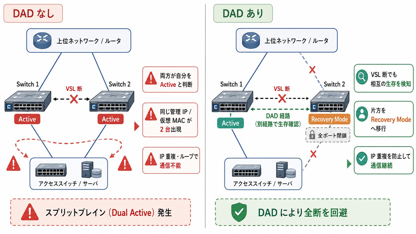
VSS 構築であわせて検討したいのが Dual Active Detection(DAD)です。これは、VSL がすべて切断された際に通信が全断するのを防ぐための仕組みです。
DAD を設定していない状態で VSL がすべて切れると、両筐体が「自分が Active だ」と判断する状況が起こり得ます(Dual Active/スプリットブレイン)。同じ IP アドレス・仮想 MAC アドレスを持つスイッチが 2 台出現するため、IP 重複やループにより通信不能に陥ります。
DAD は、VSL とは別の経路で生存確認を行い、VSL が切れても相互の生存を検知できるようにする仕組みです。検知時には片方を Recovery Mode(全ポート閉鎖)に移行させ、IP 重複を防ぎます。スプリットブレインによる全断を避けるため、DAD の併用が推奨されます。
Catalyst 4500-X で一般的な Fast-Hello 方式の設定例を示します。VSL とは別に直結ケーブルを 1 本用意して設定します。
グローバル設定(ドメイン内):
Switch(config)# switch virtual domain 100
Switch(config-vs-domain)# dual-active detection fast-hello
Switch(config-vs-domain)# exit
インターフェース設定(例: Te1/1/10 と Te2/1/10)。このポートはデータ通信には使えなくなります。
Switch(config)# interface range tenGigabitEthernet 1/1/10 , tenGigabitEthernet 2/1/10
Switch(config-if-range)# shutdown
Switch(config-if-range)# dual-active fast-hello
Switch(config-if-range)# no shutdown
Switch(config-if-range)# end
これで、VSL が切れた場合でも Fast-Hello リンク経由でどちらが Recovery Mode に入るかを決定できるようになります。
参照: Cisco Catalyst 4500 Series VSS 設定ガイド(https://www.cisco.com/c/en/us/td/docs/switches/lan/catalyst4500/XE3-8-0E/15-24E/configuration/guide/xe-380-configuration/vss.html)
設定と再起動が完了したら、役割・リンク・DAD の 3 点が正常かを確認します。
VSS のステータス確認:
Switch# show switch virtualLocal switch と Peer switch がそれぞれ認識され、片方が Active、もう片方が Standby になっていれば正常です。
Executing the command on VSS member switch role = VSS Active, id = 1
Switch mode                  : Virtual Switch
Virtual switch domain number : 100
Local switch number          : 1
Local switch operational role: Virtual Switch Active
Peer switch number           : 2
Peer switch operational role : Virtual Switch Standby
VSL(リンク)の確認:
Switch# show switch virtual linkVSL Status : UP であることを確認します。ここが Down だと同期が取れません。
Executing the command on VSS member switch role = VSS Active, id = 1
VSL Status : UP
VSL Uptime : 7 minutes
VSL Control Link : Te1/1/1
Dual Active Detection(DAD)の確認:
Switch# show switch virtual dual-active fast-hello検知が enabled: Yes になっており、ポートが Dual Active Capable であることを確認します。
Executing the command on VSS member switch role = VSS Active, id = 1
Fast-hello dual-active detection enabled: Yes
Fast-hello dual-active interfaces:
Port       Local State                Peer Port
---------------------------------------------------
Te1/1/10   Dual Active Capable       Te2/1/10
あわせて show redundancy で、冗長モードが Stateful Switchover、Standby が STANDBY HOT であることを確認しておくと、同期状態の裏取りになります。
VSS・StackWise Virtual・Nexus vPC の違いと移行の考え方
マルチシャーシでリンクを集約する技術には、VSS のほかに StackWise Virtual(SVL)や Nexus の vPC があります。それぞれ設計思想が異なるため、用途に応じた選定が必要です。
| 項目 | VSS(Catalyst 4500-X/6500) | StackWise Virtual(Catalyst 9000) | vPC(Nexus) |
|---|---|---|---|
| 制御プレーン | 1 つに統合 | 1 つに統合 | 各筐体で独立(2 つ) |
| 管理 IP | 1 つ | 1 つ | 各筐体で別 |
| 同期リンク | VSL | SVL(Stackwise Virtual Link) | peer-link + keepalive |
| 主な用途 | キャンパスのコア/ディストリ | キャンパス(VSS の後継) | データセンター |
| 位置づけ | サポート終了済み | 現行 | 現行(DC 向け) |
VSS と SVL は制御プレーンを 1 つに統合するため、運用はシンプルになる一方で、ソフトウェア更新時は両筐体が同時に影響を受ける設計です。これに対し vPC は各筐体が独立した制御プレーンを保つため、片側ずつ保守しやすいという違いがあります。Nexus 環境での同等構成については、関連記事『Cisco Nexus 9000 vPC 設定のベストプラクティスと VSS との違い』もあわせて参照してください。
Catalyst 4500-X のサポート状況と移行先
新規構築や更改を検討する場合、Catalyst 4500-X のライフサイクルは重要な判断材料です。公式の EOL 告知によると、Catalyst 4500-X シリーズはエンドオブセールが 2020 年 10 月 30 日、最終サポート日(Last Date of Support)が 2025 年 10 月 31 日です。セキュリティ脆弱性サポートの終了日も同じく 2025 年 10 月 31 日に設定されており、現時点では公式サポートが終了しています。
このため、これから冗長構成を新規に組むのであれば、後継となる Catalyst 9000 シリーズ(9400/9500)と、その StackWise Virtual(SVL)構成を前提に設計することが現実的です。SVL の設定手順や VSS との違いは、関連記事『Catalyst 9000 StackWise Virtual 設定の手順|SVL と DAD のポイント』で整理しています。既存の 4500-X VSS を運用中の場合も、保守契約とリスクを踏まえた移行計画の検討が推奨されます。
参考: End-of-Sale and End-of-Life Announcement for the Cisco Catalyst 4500-X Series Switches
“Last Date of Support: HW … October 31, 2025”
(ハードウェアの最終サポート日は 2025 年 10 月 31 日)
https://www.cisco.com/c/en/us/products/collateral/switches/catalyst-4500-x-series-switches/eos-eol-notice-c51-743098.html
まとめ
本記事では、Catalyst 4500-X における VSS の設定手順と、運用上の注意点を整理しました。VSL の構成要件やコンバージョン時の挙動、スプリットブレイン対策まで押さえておくと、構築時のつまずきを減らせます。製品のサポート状況も踏まえ、移行も含めた判断材料としてご活用ください。
- VSS は 2 台の物理スイッチを論理的に 1 台として扱う冗長化技術
- VSL は LACP を使わず
mode onで構成するのが要件 - コンバージョンは再起動を伴うため、メンテナンス枠での実施が無難
- プリエンプション非対応で、先に起動した側が Active になる
- スプリットブレイン対策として Dual Active Detection の併用が有効
- 確認は show switch virtual/link/dual-active fast-hello の 3 点が基本
- Catalyst 4500-X はサポート終了済みで、後継は Catalyst 9000 の StackWise Virtual
以上、最後までお読みいただきありがとうございました。